Klik untuk perbesar
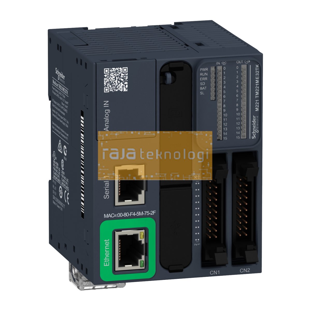
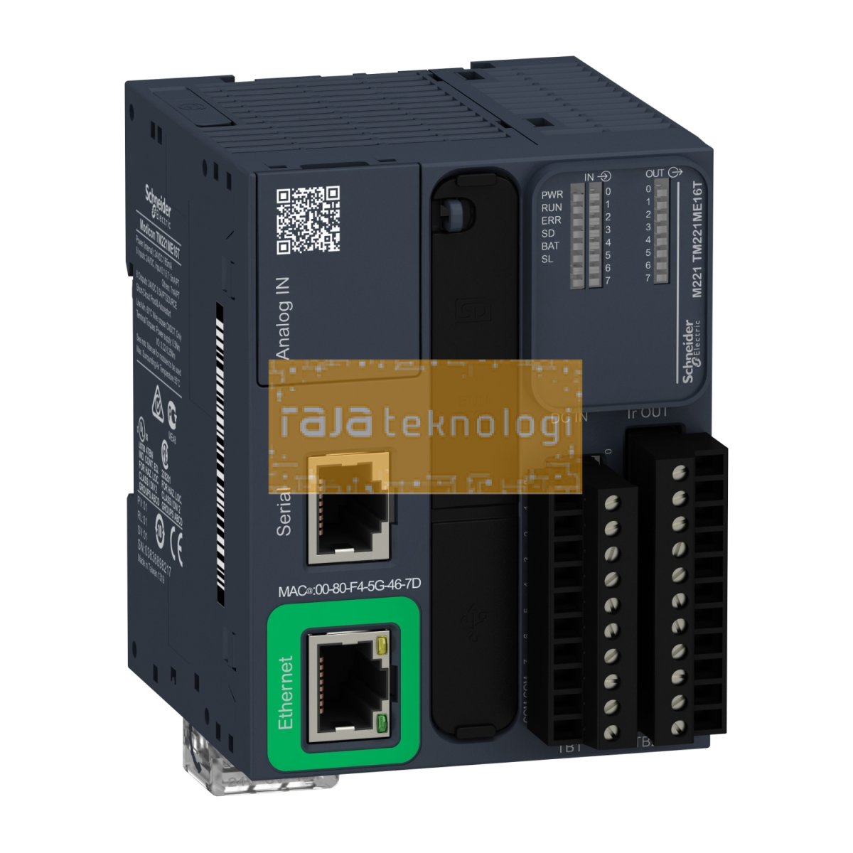
| Kode Produk | TM221ME16T |
| Brand | Schneider |
| Kategori | PLC & I/O Module |
Pengiriman ke seluruh Indonesia via ekspedisi terpercaya
| Range of product | Modicon M221 |
|---|---|
| Product or component type | Logic controller |
| [Us] rated supply voltage | 24 V DC |
| Discrete input number | 8, discrete input 4 fast input conforming to IEC 61131-2 Type 1 |
| Analogue input number | 2 at 0...10 V |
| Discrete output type | Transistor |
| Discrete output number | 8 transistor 2 fast output |
| Discrete output voltage | 24 V DC |
| Discrete output current | 0.5 A |
| Discrete I/O number | 16 |
|---|---|
| Maximum number of I/O expansion module | 7 (local I/O-Architecture) 14 (remote I/O-Architecture) |
| Supply voltage limits | 20.4…28.8 V |
| Inrush current | 35 A |
| Maximum power consumption in W | 22.9 W at 24 V (with max number of I/O expansion module) 4 W at 24 V (without I/O expansion module) |
| Power supply output current | 0.52 A 5 V for expansion bus 0.49 A 24 V for expansion bus |
| Discrete input logic | Sink or source (positive/negative) |
| Discrete input voltage | 24 V |
| Discrete input voltage type | DC |
| Analogue input resolution | 10 bits |
| LSB value | 10 mV |
| Conversion time | 1 ms per channel + 1 controller cycle time for analogue input analog input |
| Permitted overload on inputs | +/- 30 V DC for 5 min (maximum) for analog input +/- 13 V DC (permanent) for analog input |
| Voltage state 1 guaranteed | >= 15 V for input |
| Voltage state 0 guaranteed | <= 5 V for input |
| Discrete input current | 7 mA for discrete input 5 mA for fast input |
| Input impedance | 100 kOhm for analog input 3.4 kOhm for input 4.9 kOhm for fast input |
| Response time | 35 µs turn-off, I2...I5 terminal(s) for input 5 µs turn-on, I0, I1, I6, I7 terminal(s) for fast input 35 µs turn-on, other terminals terminal(s) for input 5 µs turn-off, I0, I1, I6, I7 terminal(s) for fast input 100 µs turn-off, other terminals terminal(s) for input 5 µs turn-on, turn-off, Q0...Q1 terminal(s) for output 50 µs turn-on, turn-off, Q2...Q3 terminal(s) for output 300 µs turn-on, turn-off, other terminals terminal(s) for output |
| Configurable filtering time | 0 ms for input 3 ms for input 12 ms for input |
| Discrete output logic | Positive logic (source) |
| Maximum current per output common | 4 A |
| Output frequency | 100 kHz for fast output (PWM/PLS mode) at Q0...Q1 5 kHz for output at Q2...Q3 0.1 kHz for output at Q4...Q6 |
| Absolute accuracy error | +/- 1 % of full scale for analog input |
| Maximum leakage current | 0.1 mA for transistor output |
| Maximum voltage drop | <1 V |
| Mechanical durability | 20000000 cycles for transistor output |
| Maximum tungsten load | <12 W for output and fast output |
| Protection type | Short-circuit and overload protection with automatic reset Short-circuit protection on output Overload and short-circuit protection at 1 A |
| Reset time | 1 s automatic reset |
| Memory capacity | 256 kB for user application and data RAM with 10000 instructions 256 kB for internal variables RAM |
| Data backed up | 256 kB built-in flash memory for backup of application and data |
| Data storage equipment | 2 GB SD card (optional) |
| Battery type | BR2032 or CR2032X lithium non-rechargeable |
| Backup time | 1 year at 25 °C (by interruption of power supply) |
| Execution time for 1 KInstruction | 0.3 ms for event and periodic task 0.7 ms for other instruction |
| Execution time per instruction | 0.2 µs Boolean |
| Exct time for event task | 60 µs response time |
| Application structure | 1 cyclic auxiliary task 1 configurable freewheeling/cyclic master task 8 interrupt tasks |
| Maximum size of object areas | 512 %M memory bits 512 %KW constant words 8000 %MW memory words 255 %TM timers 255 %C counters |
| Realtime clock | With |
| Clock drift | <= 30 s/month at 25 °C |
| Regulation loop | Adjustable PID regulator up to 14 simultaneous loops |
| Positioning functions | Position PTO 2 axe(s)pulse/direction mode (100 kHz) Position PTO 1 axe(s)CW/CCW mode (100 kHz) |
| Function available | PLS Frequency generator PWM |
| Counting input number | 4 fast input (HSC mode) at 100 kHz 32 bits |
| counter function | Pulse/direction A/B Single phase |
| Integrated connection type | USB port with mini B USB 2.0 connector Non isolated serial link serial 1 with RJ45 connector and RS232/RS485 interface Ethernet with RJ45 connector |
| Supply | (serial 1)serial link supply: 5 V, <200 mA |
| Transmission rate | 1.2...115.2 kbit/s (115.2 kbit/s by default) for bus length of 15 m for RS485 1.2...115.2 kbit/s (115.2 kbit/s by default) for bus length of 3 m for RS232 480 Mbit/s for USB |
| Communication port protocol | USB port: USB - SoMachine-Network Non isolated serial link: Modbus master/slave - RTU/ASCII or SoMachine-Network Ethernet |
| Port Ethernet | 10BASE-T/100BASE-TX 1 port with 100 m copper cable |
| Communication service | DHCP client Ethernet/IP adapter Modbus TCP server Modbus TCP slave device Modbus TCP client |
| Local signalling | 1 LED (green) for PWR 1 LED (green) for RUN 1 LED (red) for module error (ERR) 1 LED (green) for SD card access (SD) 1 LED (red) for BAT 1 LED per channel (green) for I/O state 1 LED (green) for SL Ethernet network activity (green) for ACT Ethernet network link (yellow) for Link (Link Status) |
| Electrical connection | terminal block, 3 terminal(s) for connecting the 24 V DC power supply connector, 4 terminal(s) for analogue inputs Mini B USB 2.0 connector for a programming terminal removable screw terminal block, 10 terminal(s) for inputs removable screw terminal block, 11 terminal(s) for outputs |
| Maximum cable distance between devices | Shielded cable: <10 m for fast input Unshielded cable: <30 m for output Unshielded cable: <30 m for digital input Unshielded cable: <1 m for analog input Shielded cable: <3 m for fast output |
| Insulation | Between input and internal logic at 500 V AC Between fast input and internal logic at 500 V AC Non-insulated between inputs Between output and internal logic at 500 V AC Non-insulated between analogue input and internal logic Non-insulated between analogue inputs |
| Marking | CE |
| Mounting support | Top hat type TH35-15 rail conforming to IEC 60715 Top hat type TH35-7.5 rail conforming to IEC 60715 plate or panel with fixing kit |
| Height | 90 mm |
| Depth | 70 mm |
| Width | 70 mm |
| Net weight | 0.264 kg |